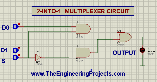
2 To 1 Multiplexer Using Logic Gates In Proteus Isis The Engineering

Find inspiration for 2 To 1 Multiplexer Using Logic Gates In Proteus Isis The Engineering with our image finder website, 2 To 1 Multiplexer Using Logic Gates In Proteus Isis The Engineering is one of the most popular images and photo galleries in A The Power Distribution Of The Proposed Spp Based 2 × 1 Multiplexer At Gallery, 2 To 1 Multiplexer Using Logic Gates In Proteus Isis The Engineering Picture are available in collection of high-quality images and discover endless ideas for your living spaces, You will be able to watch high quality photo galleries 2 To 1 Multiplexer Using Logic Gates In Proteus Isis The Engineering.
aiartphotoz.com is free images/photos finder and fully automatic search engine, No Images files are hosted on our server, All links and images displayed on our site are automatically indexed by our crawlers, We only help to make it easier for visitors to find a free wallpaper, background Photos, Design Collection, Home Decor and Interior Design photos in some search engines. aiartphotoz.com is not responsible for third party website content. If this picture is your intelectual property (copyright infringement) or child pornography / immature images, please send email to aiophotoz[at]gmail.com for abuse. We will follow up your report/abuse within 24 hours.
Related Images of 2 To 1 Multiplexer Using Logic Gates In Proteus Isis The Engineering
A The Power Distribution Of The Proposed Spp Based 2 × 1 Multiplexer At
A The Power Distribution Of The Proposed Spp Based 2 × 1 Multiplexer At
850×1172
A The Power Distribution Of The Proposed Spp Based 1 × 2
A The Power Distribution Of The Proposed Spp Based 1 × 2
850×875
Proposed 2 To 1 Multiplexer A Circuit And B Schematic Download
Proposed 2 To 1 Multiplexer A Circuit And B Schematic Download
850×1741
Simulation Parameters Of Proposed 2 × 1 Multiplexer Download
Simulation Parameters Of Proposed 2 × 1 Multiplexer Download
576×576
The Equivalent Circuits Of 21 Multiplexers Based On A Cmos And B
The Equivalent Circuits Of 21 Multiplexers Based On A Cmos And B
509×509
The Power Distribution Of The Proposed All Optical 1 × 2 Demultiplexer
The Power Distribution Of The Proposed All Optical 1 × 2 Demultiplexer
850×398
Figure 10 From Low Loss And Small 2 × 4λ Multiplexers Based On 2 × 2
Figure 10 From Low Loss And Small 2 × 4λ Multiplexers Based On 2 × 2
568×862
Schematic Diagram Of A 2 To 1 Multiplexer 19 Download Scientific
Schematic Diagram Of A 2 To 1 Multiplexer 19 Download Scientific
439×558
A The Proposed Substrate Integrated Spoof Spp Tl That Consists Of
A The Proposed Substrate Integrated Spoof Spp Tl That Consists Of
850×1042
161 Multiplexer Using 21 Multiplexers Download Scientific Diagram
161 Multiplexer Using 21 Multiplexers Download Scientific Diagram
850×505
Figure 3 From A 2×25gbs 20mw Serializing Transmitter With 251
Figure 3 From A 2×25gbs 20mw Serializing Transmitter With 251
702×436
To Implement A Half Subtractor The Minimum Number Of 2×1 Multiplexers
To Implement A Half Subtractor The Minimum Number Of 2×1 Multiplexers
1335×793
The Equivalent Circuits Of 21 Multiplexers Based On A Cmos And B
The Equivalent Circuits Of 21 Multiplexers Based On A Cmos And B
850×277
Multiplexer In Digital Electronics Block Diagram Designing And Logic
Multiplexer In Digital Electronics Block Diagram Designing And Logic
2048×1639
Figure 7 From Low Power Application For Nano Scaled Memristor Based 2∶1
Figure 7 From Low Power Application For Nano Scaled Memristor Based 2∶1
696×858
Low Power Ptl Based Multiplexer Design In ±09v 32nm Dual Gate Si
Low Power Ptl Based Multiplexer Design In ±09v 32nm Dual Gate Si
938×738
21 Mux Using Cmos Logic Only Download Scientific Diagram
21 Mux Using Cmos Logic Only Download Scientific Diagram
850×569
The Equivalent Circuits Of 21 Multiplexers Based On A Cmos And B
The Equivalent Circuits Of 21 Multiplexers Based On A Cmos And B
640×640
Solved Write Vhdl Programs For A 4x1 Multiplexer Using 2x1
Solved Write Vhdl Programs For A 4x1 Multiplexer Using 2x1
538×394
E Y Component Vm Distribution On The Y Pattern Spp Mode Power
E Y Component Vm Distribution On The Y Pattern Spp Mode Power
686×384
16 × 1 Multiplexer Using 8 × 1 And 2 × 1 Multiplexers Download
16 × 1 Multiplexer Using 8 × 1 And 2 × 1 Multiplexers Download
567×600
The Comparisons Of The Cost Function Values Of The Proposed Spp
The Comparisons Of The Cost Function Values Of The Proposed Spp
850×669
Figure 1 From A New Low Power Rtd Based 41 Multiplexer Ic Using An Inp
Figure 1 From A New Low Power Rtd Based 41 Multiplexer Ic Using An Inp
690×546
Figure 4 From A 2×25gbs 20mw Serializing Transmitter With 251
Figure 4 From A 2×25gbs 20mw Serializing Transmitter With 251
698×380
Circuit Diagram For Multiplexer Circuit Diagram
Circuit Diagram For Multiplexer Circuit Diagram
556×258
16 × 1 Multiplexer Using 8 × 1 And 2 × 1 Multiplexers Download
16 × 1 Multiplexer Using 8 × 1 And 2 × 1 Multiplexers Download
568×568
2 To 1 Multiplexer Using Logic Gates In Proteus Isis The Engineering
2 To 1 Multiplexer Using Logic Gates In Proteus Isis The Engineering
541×284
Multiplexer What Is It And How Does It Work Electrical4u
Multiplexer What Is It And How Does It Work Electrical4u
698×535
