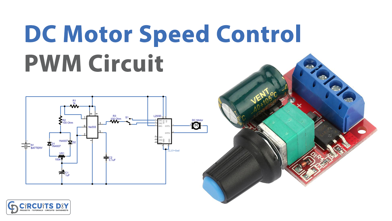
Pwm Dc Motor Control Circuit Diagram Explained

Find inspiration for Pwm Dc Motor Control Circuit Diagram Explained with our image finder website, Pwm Dc Motor Control Circuit Diagram Explained is one of the most popular images and photo galleries in Pwm Pwm Scheme 2 Level 3 Level Current Ripple Motor Heating Gallery, Pwm Dc Motor Control Circuit Diagram Explained Picture are available in collection of high-quality images and discover endless ideas for your living spaces, You will be able to watch high quality photo galleries Pwm Dc Motor Control Circuit Diagram Explained.
aiartphotoz.com is free images/photos finder and fully automatic search engine, No Images files are hosted on our server, All links and images displayed on our site are automatically indexed by our crawlers, We only help to make it easier for visitors to find a free wallpaper, background Photos, Design Collection, Home Decor and Interior Design photos in some search engines. aiartphotoz.com is not responsible for third party website content. If this picture is your intelectual property (copyright infringement) or child pornography / immature images, please send email to aiophotoz[at]gmail.com for abuse. We will follow up your report/abuse within 24 hours.
Related Images of Pwm Dc Motor Control Circuit Diagram Explained
Pwm Pwm Scheme 2 Level 3 Level Current Ripple Motor Heating
Pwm Pwm Scheme 2 Level 3 Level Current Ripple Motor Heating
617×231
Current Ripple Of The A Two Level And B Three Level Pwm Top
Current Ripple Of The A Two Level And B Three Level Pwm Top
850×274
Current Ripple Nms For An H Bridge Dc Pwm 2 3 And 4 Levels
Current Ripple Nms For An H Bridge Dc Pwm 2 3 And 4 Levels
850×645
Ac Pwm Current Ripple Nms For 2 And 3 Levels With Their Bessel
Ac Pwm Current Ripple Nms For 2 And 3 Levels With Their Bessel
674×506
Pwm Pwm Scheme 2 Level 3 Level Current Ripple Motor Heating
Pwm Pwm Scheme 2 Level 3 Level Current Ripple Motor Heating
768×1024
3 Level Pwm Vs 2 Level Pwm Granite Devices Knowledge Wiki
3 Level Pwm Vs 2 Level Pwm Granite Devices Knowledge Wiki
800×520
Pwm Power Stage Current Ripple And Motor Chokes Maxon Support
Pwm Power Stage Current Ripple And Motor Chokes Maxon Support
1197×970
Pwm Power Stage Current Ripple And Motor Chokes Maxon Support
Pwm Power Stage Current Ripple And Motor Chokes Maxon Support
1194×670
3 Level Pwm Vs 2 Level Pwm Granite Devices Knowledge Wiki
3 Level Pwm Vs 2 Level Pwm Granite Devices Knowledge Wiki
861×625
3 Phase 2 Level Inverter A Schematic B Pwm Waveform With
3 Phase 2 Level Inverter A Schematic B Pwm Waveform With
850×455
Pwm Scheme And Current Ripple Of Switching Power
Pwm Scheme And Current Ripple Of Switching Power
768×994
Three‐level Phase‐disposition Pwm Method Download Scientific Diagram
Three‐level Phase‐disposition Pwm Method Download Scientific Diagram
721×677
Digital Control Solution For 3 Level Inverters Renesas
Digital Control Solution For 3 Level Inverters Renesas
1135×540
3 Level Pwm Vs 2 Level Pwm Granite Devices Knowledge Wiki
3 Level Pwm Vs 2 Level Pwm Granite Devices Knowledge Wiki
864×636
On The Heating Of Motors In Hand Held Tools Maxon Support
On The Heating Of Motors In Hand Held Tools Maxon Support
766×322
Modified Pwm Scheme For An H Bridge Single Phase 3 Level Inverter That
Modified Pwm Scheme For An H Bridge Single Phase 3 Level Inverter That
850×847
Remote State Pwm With Minimum Rms Torque Ripple And Reduced Common Mode
Remote State Pwm With Minimum Rms Torque Ripple And Reduced Common Mode
1889×1069
8 Illustration Of The Unipolar Pwm Method For The Three Level Npc
8 Illustration Of The Unipolar Pwm Method For The Three Level Npc
850×1090
Pwm Strategy A Sine And Triangular Waveform B S1s4 Pwm Pulses C
Pwm Strategy A Sine And Triangular Waveform B S1s4 Pwm Pulses C
850×741
Ls Pwm Scheme For The Proposed Topology Ls Level Shifted Pwm Pulse
Ls Pwm Scheme For The Proposed Topology Ls Level Shifted Pwm Pulse
640×640
Figure 1 From The Generalized Discontinuous Pwm Scheme For Three Phase
Figure 1 From The Generalized Discontinuous Pwm Scheme For Three Phase
908×1074
Pwm Dc Motor Control Circuit Diagram Explained
Pwm Dc Motor Control Circuit Diagram Explained
1280×720
Figure 7 From An Improved Phase Shifted Pwm Method For A Three Phase
Figure 7 From An Improved Phase Shifted Pwm Method For A Three Phase
1342×706
Schematic Diagram Of A Two Level Three Phase Pwm Voltage Source
Schematic Diagram Of A Two Level Three Phase Pwm Voltage Source
703×413
Three Level Shifted Carrier Pwm H Bridge Structure 11 With Related
Three Level Shifted Carrier Pwm H Bridge Structure 11 With Related
455×527
What Is Pulse Width Modulation Pwm Electrical Engineering News And
What Is Pulse Width Modulation Pwm Electrical Engineering News And
640×442
Introduction To Pwm Pulse Width Modulation The Engineering Projects
Introduction To Pwm Pulse Width Modulation The Engineering Projects
2718×1456
