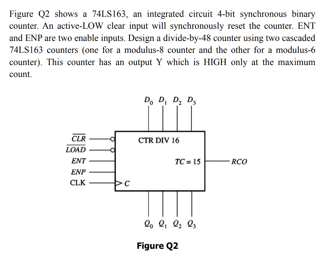
Solved Figure Q2 Shows A 74ls163 An Integrated Circuit

Find inspiration for Solved Figure Q2 Shows A 74ls163 An Integrated Circuit with our image finder website, Solved Figure Q2 Shows A 74ls163 An Integrated Circuit is one of the most popular images and photo galleries in Solved Figure Q2 Shows A 74ls163 An Integrated Circuit Gallery, Solved Figure Q2 Shows A 74ls163 An Integrated Circuit Picture are available in collection of high-quality images and discover endless ideas for your living spaces, You will be able to watch high quality photo galleries Solved Figure Q2 Shows A 74ls163 An Integrated Circuit.
aiartphotoz.com is free images/photos finder and fully automatic search engine, No Images files are hosted on our server, All links and images displayed on our site are automatically indexed by our crawlers, We only help to make it easier for visitors to find a free wallpaper, background Photos, Design Collection, Home Decor and Interior Design photos in some search engines. aiartphotoz.com is not responsible for third party website content. If this picture is your intelectual property (copyright infringement) or child pornography / immature images, please send email to aiophotoz[at]gmail.com for abuse. We will follow up your report/abuse within 24 hours.
Related Images of Solved Figure Q2 Shows A 74ls163 An Integrated Circuit
Solved Figure Q2 Shows A 74ls163 An Integrated Circuit
Solved Figure Q2 Shows A 74ls163 An Integrated Circuit
1024×851
Solved 2 Figure Q2 Shows A 74ls163 An Integrated Circuit
Solved 2 Figure Q2 Shows A 74ls163 An Integrated Circuit
700×434
Solved Q2 Using 74ls163 4 Bit Binary Counter And Any
Solved Q2 Using 74ls163 4 Bit Binary Counter And Any
700×262
Solved Q14 74ls163 is An Integrated Circuit 4 Bit
Solved Q14 74ls163 is An Integrated Circuit 4 Bit
1822×1133
74ls163 Fully Synchronous 4 Bit Counter Datasheet Hub
74ls163 Fully Synchronous 4 Bit Counter Datasheet Hub
720×523
Solved Counter Circuit 74ls163 Figure 2 10 Pts Draw The
Solved Counter Circuit 74ls163 Figure 2 10 Pts Draw The
1024×554
Solved 6 7 All Necessary Information On The 74ls163
Solved 6 7 All Necessary Information On The 74ls163
731×1024
Solved Using 74ls163 4 Bit Binary Counter And Any Necessary
Solved Using 74ls163 4 Bit Binary Counter And Any Necessary
571×700
Solved Show The Connection For The 74x163 To Count From 3 To
Solved Show The Connection For The 74x163 To Count From 3 To
707×482
Solved D Use The 74ls163 Counter Ic See Figure Below To
Solved D Use The 74ls163 Counter Ic See Figure Below To
730×401
Solved Figure Q2 Shows The Circuit Diagram Of A Test To
Solved Figure Q2 Shows The Circuit Diagram Of A Test To
1222×840
Solved 2 Counter Circuit 74ls163 Figure 2 10 Pts Draw The
Solved 2 Counter Circuit 74ls163 Figure 2 10 Pts Draw The
819×411
Solved Figure Q2 Consider The Circuit In Figure Q2 The
Solved Figure Q2 Consider The Circuit In Figure Q2 The
1042×990
Solved Text Question Three 25 Marks A Use A 74ls151 Multiplexer To
Solved Text Question Three 25 Marks A Use A 74ls151 Multiplexer To
756×591
Solved Can The 74ls163 Be Used As A Bcd Counter Show The Wiring
Solved Can The 74ls163 Be Used As A Bcd Counter Show The Wiring
1700×1855
Solved Figure Q2 Shows The Circuit Diagram Of Part Of An
Solved Figure Q2 Shows The Circuit Diagram Of Part Of An
636×650
Solved For The Circuit Shown In Figure Q2 Answer The
Solved For The Circuit Shown In Figure Q2 Answer The
615×1013
Solved Figure Q21 Shows A Circuit That Displays A Signed
Solved Figure Q21 Shows A Circuit That Displays A Signed
554×700
Solved Can The 74ls163 Be Used As A Bcd Counter Show The Wiring
Solved Can The 74ls163 Be Used As A Bcd Counter Show The Wiring
1700×600
Solved 2 Figure Q2 Shows An Operational Amplifier Con
Solved 2 Figure Q2 Shows An Operational Amplifier Con
789×771
Solved Figure Q2 Shows A De Circuit With A Resistive Load
Solved Figure Q2 Shows A De Circuit With A Resistive Load
700×436
Solved Q2 Figure Q2 Shows The Circuit Of An Astable
Solved Q2 Figure Q2 Shows The Circuit Of An Astable
724×432
Solved The Circuit Below Uses A Free Running Counter 74ls163 And A
Solved The Circuit Below Uses A Free Running Counter 74ls163 And A
700×597
Solved Determine The Modified Modulus Number Of States Of The Reset
Solved Determine The Modified Modulus Number Of States Of The Reset
1024×276
Solved Determine The Modulus Of The Following Counters Composed Of
Solved Determine The Modulus Of The Following Counters Composed Of
526×302
Solved Figure Q2dii Shows A Clipper Circuit Using S
Solved Figure Q2dii Shows A Clipper Circuit Using S
514×721
Solved Figure Q2 Shows A Series Rlc Circuit With An
Solved Figure Q2 Shows A Series Rlc Circuit With An
719×839
Solved The Circuit Below Uses A Frequency Running Counter 74ls163 And
Solved The Circuit Below Uses A Frequency Running Counter 74ls163 And
700×638
Solved Q2 In The Circuit Of Fig 1 The Op Amps Are Ideal Derive
Solved Q2 In The Circuit Of Fig 1 The Op Amps Are Ideal Derive
1840×1343
Solved Figure Q2c Shows An Amplifier Circuit Using
Solved Figure Q2c Shows An Amplifier Circuit Using
619×558
Solved 1 Using The 74ls163 Counter Below D Is The
Solved 1 Using The 74ls163 Counter Below D Is The
1024×767
Solved Question 26 1 0 1 0 Cep Pe Pp P2 P3 74ls163 Cet
Solved Question 26 1 0 1 0 Cep Pe Pp P2 P3 74ls163 Cet
700×513
Solved Can The 74ls163 Be Used As A Bcd Counter Show The Wiring
Solved Can The 74ls163 Be Used As A Bcd Counter Show The Wiring
611×748
Solved 4 Using The 74ls163 Counter Shown Below And Logic
Solved 4 Using The 74ls163 Counter Shown Below And Logic
687×488
